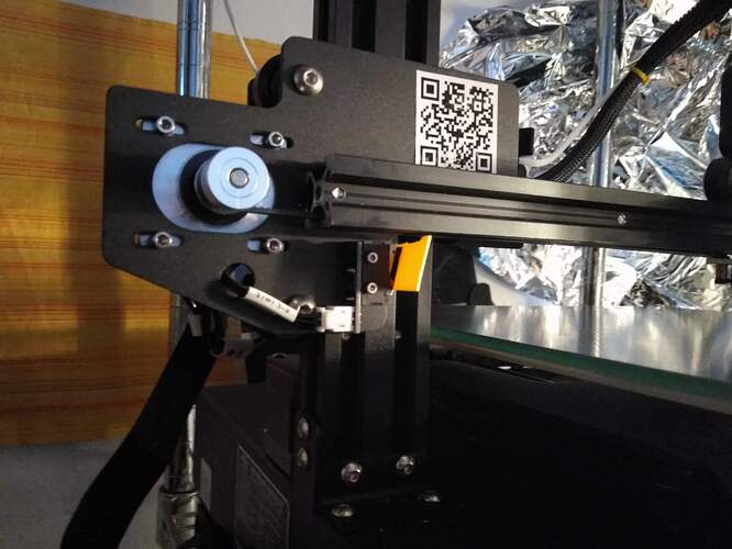
micro swiss direct extruder on Anet ET5pro

So I bought a micro swiss direct extruder kit for CR10/Ender3 with all metal hotend for my Anet ET5pro and encountered several problems:

First, the extruder carrier hit the QR code thing, so the carrier must be distanced with in my case 4x 1mm thick o-rings at each wheel. (See pic in attachments.)

Then the extruder carrier missed the x endstop, crashing, so I had to glue the yellow piece of plastic (with contact glue) to the endstop to make it work again, see pic.

Then I had to solder the extruder motor cable 180° turned around to make it extrude in the correct direction, which was not really bothering, as the cable is neatly at lenght now.

The Anet filament sensor must be reused, leave it in place together with the now motorless feeding bracket. The old press fit attachment for the bowden tube holds stirdier, don’t use the furnished micro swiss red-one, see pic.

Adapt the Cura extruder setting to 1,5mm retraction.

Now, it prints, but in the air: z axis software endstop.
So I added some o-rings to raise the tension of the springs, pushing the print bed further up. Not enough, see pics.

I lost about 1" in the y axis and - still have to check - some mm in the z axis.
And the ventilator casing holds now with only 1 screw, a fitting replacemt will be printed later.

As I bought the printer with Marlin installed, I hesitate to flash Marlin from scratch.

Would someone have the Anet ET5pro Marlin configuration file for easy compiling, wouldn’t you?
Or explain the M 206 and M 428 thing for slow ?, so that the final values saving M500 works?

Thanks for your practical support.

That’s quite a few issues to resolve.

Perhaps this video might help: [U]Adjusting Home Offsets - Marlin M428 / M206 | Reclaim lost build volume - YouTube. 1 thing I noticed is that the presenter prefers M428 to M206 & that M428 doesn’t actually move the hotend; it “locks in” the current hotend position as 0,0,0. Then, M500 stores the current configuration in firmware.

I get always a position too far away error.

What happens when you send a G0 X0 Y0 Z0 command?

The nozzle goes to xy center bed, but stays in the z axis some 2" above the print bed, the starting position for z sensor leveling.
So the too far away error would come from the z axis.


Send: M503
Recv: echo: G21 ; Units in mm (mm)
Recv: echo: M149 C ; Units in Celsius
Recv:
Recv: echo:; Filament settings: Disabled
Recv: echo: M200 S0 D1.75
Recv: echo:; Steps per unit:
Recv: echo: M92 X80.00 Y80.00 Z400.00 E100.00
Recv: echo:; Maximum feedrates (units/s):
Recv: echo: M203 X150.00 Y150.00 Z50.00 E50.00
Recv: echo:; Maximum Acceleration (units/s2):
Recv: echo: M201 X2000.00 Y2000.00 Z100.00 E10000.00
Recv: echo:; Acceleration (units/s2): P<print_accel> R<retract_accel> T<travel_accel>
Recv: echo: M204 P500.00 R3000.00 T500.00
Recv: echo:; Advanced: B<min_segment_time_us> S<min_feedrate> T<min_travel_feedrate> J<junc_dev>
Recv: echo: M205 B20000.00 S0.00 T0.00 J0.02
Recv: echo:; Home offset:
Recv: echo: M206 X0.00 Y0.00 Z0.00
Recv: echo:; Auto Bed Leveling:
Recv: echo: M420 S0 Z0.00
Recv: echo: G29 W I0 J0 Z0.73000
Recv: echo: G29 W I1 J0 Z0.36050
Recv: echo: G29 W I2 J0 Z0.08900
Recv: echo: G29 W I3 J0 Z-0.77750
Recv: echo: G29 W I0 J1 Z0.47350
Recv: echo: G29 W I1 J1 Z0.18050
Recv: echo: G29 W I2 J1 Z-0.05900
Recv: echo: G29 W I3 J1 Z-0.96050
Recv: echo: G29 W I0 J2 Z0.23300
Recv: echo: G29 W I1 J2 Z-0.02150
Recv: echo: G29 W I2 J2 Z-0.23200
Recv: echo: G29 W I3 J2 Z-1.13800
Recv: echo: G29 W I0 J3 Z0.08400
Recv: echo: G29 W I1 J3 Z-0.18950
Recv: echo: G29 W I2 J3 Z-0.41700
Recv: echo: G29 W I3 J3 Z-1.24300
Recv: echo:; Material heatup parameters:
Recv: echo: M145 S0 H210 B68 F255
Recv: echo: M145 S1 H240 B110 F0
Recv: echo:; PID settings:
Recv: echo: M301 P24.03 I2.33 D62.00
Recv: echo: M304 P77.83 I3.70 D294.74
Recv: echo:; Power-Loss Recovery:
Recv: echo: M413 S1
Recv: echo:; Z-Probe Offset (mm):
Recv: echo: M851 X-23.00 Y-10.00 Z-0.12
Recv: echo:; Filament load/unload lengths:
Recv: echo: M603 L350.00 U350.00
Recv: echo:; Filament runout sensor:
Recv: echo: M412 S1

I just did something like this to set the Z Offset of my Ender 5. I used the LCD menu to very carefully lower the nozzle down to the bed 0.1mm at a time. Since you’re at 2", I would start with 10mm a couple of times, then 1mm a few times, then 0.1mm to get really close. When you get the nozzle really close to the bed, issue the M428 & M500 commands again. After that, do a normal bed leveling.

I oversaw that you can turn off the software endstops in the printer’s control panel.

However, to fix the too low bed problem, I nutted some o-ringhs tight under the print bed with longer screws.
This gives the printbed screws perdendicular stiffness and prewvents layer shifting and ghosting.

[ATTACH=JSON]{“data-align”:“none”,“data-size”:“full”,“title”:“IMG_20210817_164156_0.jpg”,“data-attachmentid”:11278}[/ATTACH]

Interesting solution. Question: did you use rubber O-rings or metal washers?

[ATTACH=JSON]{“alt”:“Click image for larger version Name: IMG_20210820_133042_0.jpg Views: 1 Size: 564.9 KB ID: 11282”,“data-align”:“none”,“data-attachmentid”:“11282”,“data-size”:“full”,“title”:“IMG_20210820_133042_0.jpg”}[/ATTACH] There is a black M4 hex nut holding 5x large1,1mm metal washers firmly up, raising the bed together around 9mm.
The four new screws are M4x40mm

That should certainly provide strong support. Of course, it is surprising you needed to do this. Really makes me wonder if the Z Stop Switch is not where it should be.