Klipper anyone?

I don’t think my printer.cfg has an automated section that says not to edit. Or maybe it’s been added and I haven’t noticed it yet. Now you got me thinking, I do 99% of my editing on the desktop using a text editor then uploading the file to Klipper, I might be overwriting the automated section. If I edit in Mainsail I then download it to my desktop.

I have managed to print one sample square with Klipper, it was one that I downloaded from Klipper and not I don’t even remember what I was suppose to be looking at after it printer. It’s like 40mmx40mm and only wall about 2mm thick. It didn’t look to bad consider it was printed at .3mm as suggested.

Yes, editting printer.cfg and uploading the file to the Pi will overwrite the automated section. I would not recommend doing that. You don’t need to anyway. The file can be editted directly from within Mainsail. Simply browse into the Pi. The Mailsail main web page should come up. I don’t recall exactly in which section, but poke around and you should find the config files. Clicking on a file will open it in the Klipper editor. Make your changes, then click Save and Restart.

If you don’t do it this way you are more likely to lose automated setting updates to the printer.cfg. The section is created and updated every time you issue a SAVE_CONFIG.

I was using the desktop txt editor because I could see the black on white better than white on black. Plus the Mainsail editor doesn’t have. search, or least I don’t think so. I think the tab with the config files is called Machine. Maybe I can change the editor colors in preferences. From here on out I’ll do the editing in Mainsail.

I believe you can change the theme for Mainsail itself. I’m not sure the editor has any of its own color options. For searching, try Ctrl+F to open a search box.

You can edit the files on the Pi from your computer - use WinSCP. I use it from my office to edit and load files to the Pi. You can have multiple sessions open for different Pi’s if you have them.

@woodwaker_dave is correct in that you can edit the files directly using WinSCP. This has the advantage that no file copying is required. I’m not sure, though, just how much advantage this method has over just using the Mainsail/fluidd interface. I have found them to be quite adequate.

I don’t think Winscp will run on Linux. :slight_smile: I learned a good lesson, I go down today to continue configuring Klipper. When a G29 was issued it did a 100x100 3x3 probe. Looked in the printer.cfg and all the mesh stuff was gone and the bed XY max was at 100. Got that straightened out. Tried setting the z-offset using PROBE_MANUAL and when it was finished it wouldn’t save it to the printer.cfg. So I used PROBE_CALIBRATE even though it didn’t so it at the center of the bed, not sure what’s up with that. Ran a PID tune on both the extruder and bed. Now I think I’m ready to do a test print. Hopefully the worst is behind me and and I can move on to the fun stuff.

Getting everything setup is a learning experience. Now for the printing - let us know how it goes

Well it didn’t go well at all. It’s just laying the filament on the top of the bed with none to very little squish. Plus it really doesn’t matter what I set the z-offset to it’s the same. I even went as far was deleting the print.cfg file and my Marco.cfg file and started over. Went and got a new printer.cfg for the Ender 3v2 and started from scratch. When I do PROBE_CALIBRATE it moves the printed to 100x170 (I think) so I did the z-offset there. It came out to 0.850 which doesn’t make sense as everything tells me it should be a negative number. My probe is 2mm above the nozzle tip. After reading the section at Klipper on the [probe] is said the z-offset in [probe] should be the distance the nozzle is from the probe so I put in 2mm didn’t work, even tried -2. When you accept after setting the offset it comments it out in [probe] and adds it to the Don’t Touch section. I edited the print.cfg and changed the z-offset form 0.600 to 0.950 and it printed about the same. I tried doing the Manual Probe macro and it uses the center of the bed but didn’t save the offset. I’ll bet I’m missing something really simple but I sure can’t figure out what I was doing wrong. I almost put FluidPi on a SD card and see if I had better luck. Then I thought the backend would be the same so I’d probably have the same issue.

Yes. The nozzle clearance is counter-intuitive. That’s why I posted earlier that, in printer.cfg, you increase Z Offset to lower the nozzle.

And, no, it should not be a negative number. I know, I know, it doesn’t make sense, but it is what it is.

I have a suggestion: start a 20x20mm square. If it’s too high, adjust the Z Offset down using the Dashboard. You can do it interactively. You can even do it multiple times for a single square. Keep lowering it until you start to get some adhesion.

Also, when you do the PROBE_CALIBRATE, accept the value it gives you. If the probe is not centering on the bed, check printer.cfg


[safe_z_home]
home_xy_position: 160.5,137.5
speed: 50.0
z_hop: 10.0
z_hop_speed: 5.0

[bed_mesh]
speed: 30
horizontal_move_z: 10
mesh_min: 20,18
mesh_max: 175,192
probe_count: 3,3
fade_start: 1.0
mesh_pps: 2,2
algorithm: bicubic
bicubic_tension: 0.2

In particular, check home_xy_position.

Changed the safe home and now Probe_Calibrate puts the hotend over the center of the bed. re calibrated the z-offset and tried a test print. Was laying down nice lines but no stick. My glass bed takes spells of not adhering so I got out my trusty glue stick, that worked. Washed the glass plate with Dawn and started again, still not sticking on the bare glass, Creality glass plate with the black side up. Used the Z-offset in Mainsail to drop the nozzle .05 and it started adhering to the bed. Might need a tiny bit more I’ll wait till it finishes then look at the bottom. I’ll have some pictures later.

I smell progress :slight_smile: Where you’re at is typically where I get really earnest about 20mm squares. I suspect, if you leave the Z Offset where it is, you will either see gaps between the lines on infill or you will be able to easily pop the lines apart with minimal effort. That’s when I move the nozzle down a bit more, until I get a smooth, shiny, strong square.

That’s what I’ve been printing is 20x20 cubes. I’m currently printing at .3mm so the sides are still liney looking. My corners have blobs but not all the way up. More at the top and bottom. The last one I turned the retraction amount down form 7 to 5 and turned the speed up. It was better but a ways from perfect. Think I’ll squish it another .025 and see where I’m at.

Sorry, no, not cubes: 20mm X 20mm 1-layer squares. The secret is the single layer. Please review this: [U]Best method for 3D printer bed levelling - YouTube

I prefer to be a little too close and have too much “squish” than not enough - this is usually covered by the next layers. I print only on glass beds. I have found a local glass company that will cut 1/4inch plate glass for me at very low costs. I just got a replacement for my Ender 5 Plus for $22 and my Ender 5 were about $7. My problem is with PETG actually removing hunks of glass when it cools. If I uses anything for an adhesive it is cheap hairspray, a must for PETG.

I print 99% PETG, with a bed temp of 70C or 80C. Dimafix works perfectly for my PETG prints. The only post-processing needed is to wash Dimafix residue off the bottom of the prints with simple warm water.

I had never heard of that - just looked it up - reminds me of magigoo - which I have used. Had good luck,but did not like the applicator tip. I have good results with clean glass for PLA, and use an adhesive for PETG and the little ABS I have tried. Thanks for sharing your results

Dimafix is cheaper than Magigoo and works better. Apparently, I converted @irvshapiro1 to it ??
[U]Bed Adhesion Alternative to Magigoo - MakeWithTech Community Forum [U]Monoprice Mini Delta - MakeWithTech Community Forum

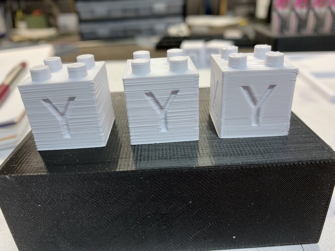
Been printing 20x20 cubes tweaking the z-offset and the slicer. I was getting them half way decent at 0.3mm so I sliced it at 0.2mm and it went to s**t almost looks like it was the other way around. The center one was with my Standard profile which is 0.2mm so the left one I printed with the Fast profile which is normally 0.3mm and all I did was change the layer height to 0.2mm. I do think some of the issues is the printer is not level, not the bed the printer, it rocks on it’s feet. This was caused by me replacing the shield over the power supply that was blocking the air exhaust for the power supply. I replaced it with one that just cover the connections. A bundle of wire pass through that area. I’m printing some TPU feet for it now to raise it 10mm which should be more than enough. I decreased the z-offset another -0.025 or actually +0.025 in Klipper’s math. I need to do a PID tune too, I’m using the setting that can in the Ender 3 v2 coffin.

[ATTACH=JSON]{“data-align”:“none”,“data-size”:“custom”,“height”:“263”,“title”:“IMG_3190.jpg”,“width”:“350”,“data-attachmentid”:14113}[/ATTACH]
The cube on the right was printed at 0.3mm the other 2 were printed at 0.2mm

[ATTACH=JSON]{“data-align”:“none”,“data-size”:“custom”,“height”:“225”,“title”:“IMG_3191.jpg”,“width”:“300”,“data-attachmentid”:14114}[/ATTACH]

[ATTACH=JSON]{“data-align”:“none”,“data-size”:“custom”,“height”:“263”,“title”:“IMG_3192.jpg”,“width”:“350”,“data-attachmentid”:14115}[/ATTACH]

[ATTACH=JSON]{“data-align”:“none”,“data-size”:“custom”,“height”:“263”,“title”:“IMG_3193.jpg”,“width”:“350”,“data-attachmentid”:14116}[/ATTACH]

[ATTACH=JSON]{“data-align”:“none”,“data-size”:“custom”,“height”:“263”,“title”:“IMG_3194.jpg”,“width”:“350”,“data-attachmentid”:14117}[/ATTACH]

Got more tweaking to do but I’m way closer than I was when I started today.

Yeah I need one of those print in the center squares, I downloaded it after I watched the video.

That really looks like layer shift. It may not be, but I would check your belt tension and ensure that the V-slot wheels don’t have any slack in them, just to be sure.