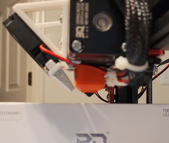
Just replaced a leaking MK8 style hotend with Biqu H2 500C direct drive extruder. Installation was easy, so wanted to share process. The H2 kit was well packaged, and included wiring, screws, tools, heater, fan, temperature sensor and interface.
H2 extruder is small, measuring only 35x35x75mm, so desired to maintain original nozzle x, y position for simplicity. By removing MK8, H2 was test fit in position. It became evident that a simple aluminum spacer could be fabricated, and H2 screwed in place with two screws.
[ATTACH=JSON]{“alt”:“Click image for larger version Name: IMG_20220709_102259.jpg Views: 2 Size: 139.1 KB ID: 15584”,“data-align”:“none”,“data-attachmentid”:“15584”,“data-size”:“small”}[/ATTACH]
Here is more on simple adapter plate. A small screw in lower left was installed with nutsert. Two holes on right, mount H2. Upper two hole are for carriage wheels.
By loosening belt tension, it is possible to flip plate forward, to install extruder without belt removal.
[ATTACH=JSON]{“data-align”:“none”,“data-size”:“small”,“data-tempid”:“temp_2227_1657399535234_857”}[/ATTACH]
Most significant work was in cooling fan mount, and related air guide to nozzle. Parts were designed to be light, and permit air flow to heat break. Air guide was designed by making measurements to get close, making draft, with changes as necessary, to get it right. Fan was mounted at 45 deg forward, for a near straight shot to nozzle. It also makes easy access to extruder thumb wheel.
[ATTACH=JSON]{“alt”:“Click image for larger version Name: 20220709_094817 (1).jpg Views: 2 Size: 1.76 MB ID: 15582”,“data-align”:“none”,“data-attachmentid”:“15582”,“data-size”:“medium”}[/ATTACH] [ATTACH=JSON]{“alt”:“Click image for larger version Name: IMG_20220708_185354.jpg Views: 2 Size: 88.0 KB ID: 15583”,“data-align”:“none”,“data-attachmentid”:“15583”,“data-size”:“medium”}[/ATTACH]
While a small section of PTFE tubing shows at top of extruder, it is just a filament guide, heat break is all metal.
The heater is a 70W unit, much greater than ~40W MK8. A 100k NTC is being used temporarily, while the PT100 interface developed. The PT100 has an OD of 4mm, and the 100K NTC only 3mm. A 3-4mm copper bushing was fabricated. Graphite was used as heat transfer, Slice paste is on order.
PID calibration resulted in stable temperature regulation.
The MKS Robin nano V1.2 control board has a MAX31855 K-type thermal couple SPI receive only interface. Sensor adapter from BTT included with is MAX31865, for PT100, it is full duplex. I purchase a K-type sensor and MAX31855 adapter. I will test and capture SPI signals with logic analyzer, and possibly use an Arduino nano V3 to interface with BTT adapter, and translate with MAX31855 emulation. That is not as hard as it sounds. An alternative is to change controller board to SKR 3, or add wire for miso, and edit MKS Robin firmware. May post more later.


