Well, I did it; I bought a Raspberry Pi 3 B+. I also bought a 3A USB adapter with a USB cable that has a pushbutton for power.
So far, I’ve installed OctoPrint & the Bed Level Visualizer. The 1st thing I printed is the 20x20 mm 1-layer squares I use to set the Z Offset. Now, it’s printing a new deflector for cat fountain. I’ll post about it in Pictures Of Your Builds.
Now, a question for everyone. What case should I print for the Pi? And, where should I install it on my Ender 5? I’m thinking it might be nice to print a case that has a couple of tabs so it can be attached, on edge, to the 4020 or 2020 frame parts, but I’m completely open to other ideas.
Hi,
On my ender5, I modified this one by adding a couple of ‘ears’:
And mount it on the front right vertical rail. This is a thin case but I like it better that the full case that I did on a different printer and it was a modded to use ears to mount it. It was also designed to contain a buck converter to supply the PI.
I have the modded files for both in Fusion 360 if they would be any help.
I got my Pi case off Thingiverse and it just sits on the desk. I took a piece of Kaplon tape and insulated the + tab in USB plug. That way the Pi doesn’t power the display.
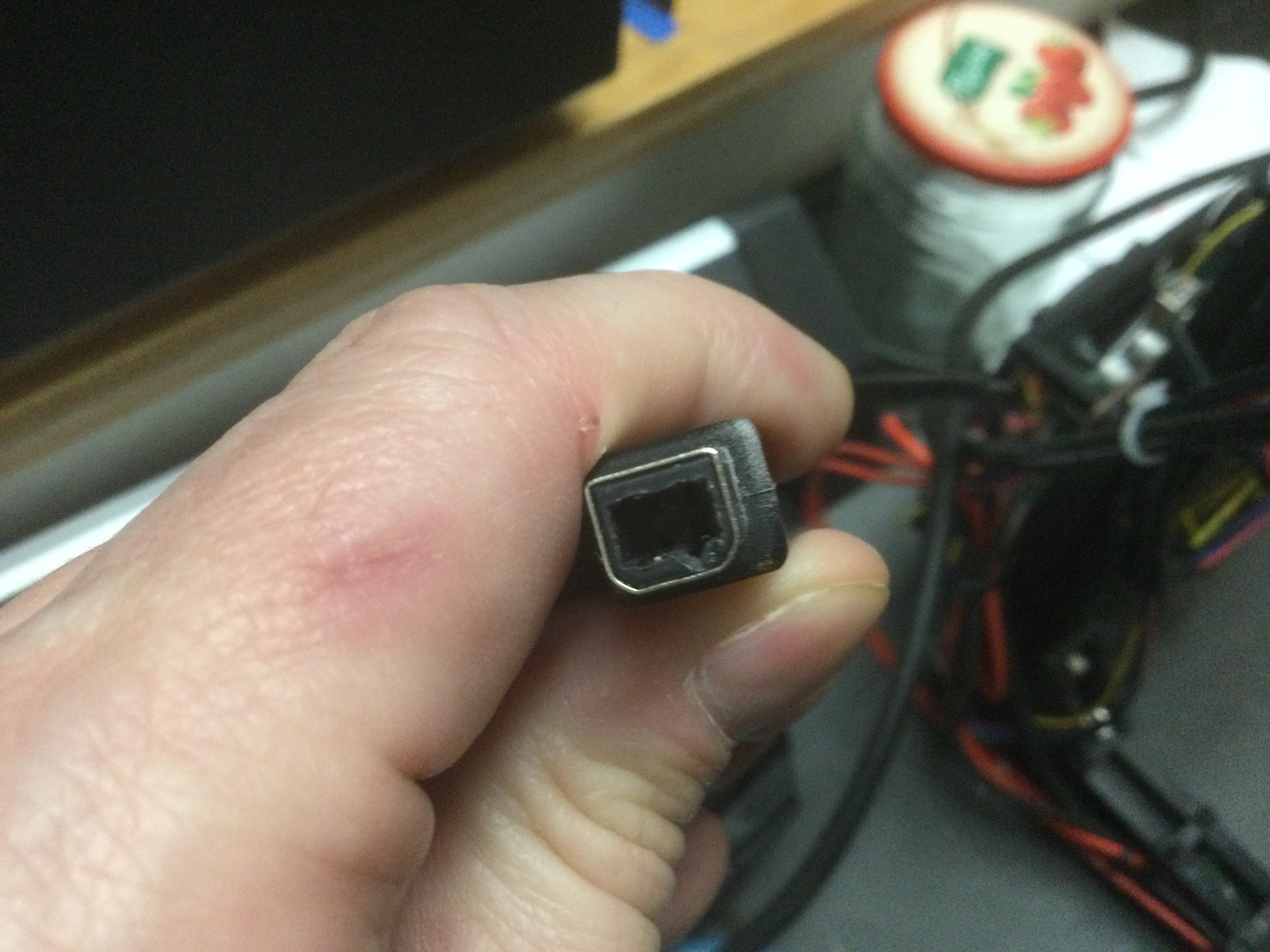
@MambaRoja, @Gramps put a piece of insulating tape over the 5V pin ‘inside’ the USB. There are 4 ways you can do it:
on the USB cable, put a piece of tape over Pin 1 in the micro-USB male connector that plugs into the printer
on the USB cable, put a piece of tape over Pin 1 in the type-A male connector at the other end of the USB cable (the 1 that plugs into the Pi)
on the Pi, place a piece of tape over Pin 1 in the female type-A connector
use a sharp Exacto knife, or similar, to actually lift up & remove the Pin 1 connector in any of the places listed above. I would recommend using this technique only on a USB cable, so as not to damage a port on a circuit board.
Here's an image from Wikipedia (pin 1 is the 5V power pin):
Great explanation @Ender5r I put the tape over pin 1 on the type connector. Kapton tape is very thin and sticky, also heat resistant. I cut a thin strip of the Kapton tape and used an Exato knife to get it inside the housing. I can try taking a picture when the printer finishes it’s current job. This is the tape I used https://www.amazon.com/gp/product/B07S485RS4/ref=ppx_yo_dt_b_search_asin_title?ie=UTF8&psc=1
I used a small wood hand drill to get behind the contact and when I was deep enough I snapped it off. Takes just a minute or so and lasts forever unlike tape, which may get rubbed in/out/off when unpluging/repluging the cable.
I did this with all my 3d printers cables. All you have to remember is that the connected device needs to have its own power supply.
I use normal PC power supplies on all of my printers. The Pi is powered by the standby-Power line and can turn on the printer in the same way as the power button does activate a pc, which is very handy. With the PSUControl plugin for octoprint the printer turns off after 15 minutes of inactivity and only if the nozzle is cool enough.
Ender5r,
Well, late morning, but at least its still morning here:})
T1 and T2 show the “Full sized” case that I have on one printer and the bottom of it is designed to also house a buck converter to power the Pi. The ears uses standard M4 screws and tee nuts to hold it to a vertical rail of the printer. Power is pulled from the main power supply for the printer and comes on when you power the whole rig up.
E1 shows the “Low height” box that I have on the other printer. Again it was modified with the ears to mount it to the vertical rail with standard hardware. In this case, It is again powered by a buck converter, but it is remotely located from the Pi but still comes on when the rig is powered. Oh and the wires coming out of the GPIO is for a filament out sensor
In both cases, couldn’t get to the other side to give a good shot!
If you still want the files, let me know and I will remove my ‘logo’ and put them up.
I have been getting undervolt errors in OctoPrint. It seems this is very common. In fact, it’s so common that there is an official Raspberry Pi AC adapter that puts out 5.1v. This seemed like a good idea to me, but I did not like that the adapter was hard-wired. It can’t be used on a Pi 3 or a Pi 4. I think it should have had a type A USB socket so a regular USB cable could be used.
I received it today. I dug around in my AC adapter boxes and found 1 that puts out 12v 5A. It had a funky 4-pin DIN type connector. I have no idea what it was used for. I plugged it in & did a pin-out. It turned out to be a waste of time. When I cut the connector off, I found that the cable only had 2 wires: 12v & ground. Bonus. I connected the wires to the buck converter & powered it up. Sure enough, the LED display read 12.65v. Excellent. I turned the output voltage pot counter clockwise a bunch of times to get the output voltage down to 5.11v. Then I cut the USB A connector off my Pi power cable & wired it up to the output of the buck converter & powered up. And voila, no undervolt message in OctoPrint!
At some point I may mount it inside the power cabinet of my Ender 5 & connect it up to the 24v PSU. I may mount the Pi in there too (if there’s room), but then I have to figure out how I’m going to keep the camera connected. I a pretty long ribbon cable that I bought with the Pi Cam, but I’m not sure it would be long enough.
Bottom line, it’s working – the voltage is rock steady.
Yep, exact reason I used buck converters on both my printers! I tied them into the main power supply for the printer and now there are no extra switches or plugs that I have to find a space for!
For anybody else, make sure the wire from the converter is sized big enough to carry the current. Don’t use any ole charger bit. Don’t ask how I know:})
I agree with that advice. In my case, fortunately, I used the USB cable with the power push button that was provided in the Pi kit. That way I can power off the Pi when needed.