I see the rubber layer under my build plate can withstand 130C, so I have plenty of room to experiment with. While the SHT30 is rated to 125C, the inexpensive cased device I’m using is only rated to 60C, so I’ll need to come up with another, probably bare, sensor to do substantial testing around this temperature.
Edit: I came up with a cheap point and shoot IR thermometer instead (Etekcity 749, around $20.) No complaint from my wife when I explained its cooking applications.
I’m running a large print which fortunately has a hole right in the center. The build plate surface is set to 60C and reads 59C in the center, dropping off to ~44C an inch in from the edges. This would explain adhesion problems in the corners of large prints, but the original issue (extended elephant foot to the 4th layer and beyond) doesn’t come down to build plate temperature, as I can repro it with small prints.
Update on this issue:
(True Confessions) I incorporated a systematic error in calibrating my e-esteps. I did it over and over, the wrong way each time.
I finally got them zeroed in and printed my nicest Benchy in a long time; both clean and strong.
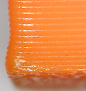
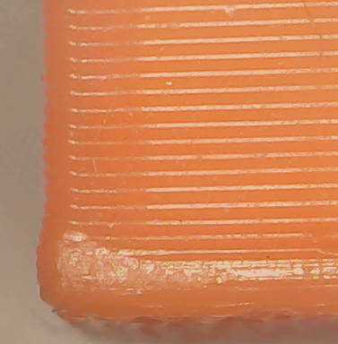
I still have the original issue; in the picture I’ve included below, the first layer is fine, it’s 2 - 6 that are bulging out, so first layer fixes don’t seem effective.
I found this, which may explain a lot: Flow calibration · 5axes/Calibration-Shapes Wiki · GitHub
Cura uses a simple, rectangular approximation of the extrusion, Prusa takes the bulge of each line into account.
I’m going to give PrusaSlicer a go, I’ll report back if it makes a difference.
Thanks, ender5r. I was just looking at Irv’s video about IdeaMaker.
I was thinking this morning:
I have a CR Touch (like a BL Touch, but newer) that can reliably measure 100’s of a mm, but has a very rounded tip.
What if I printed an extension tip for the probe with a fine point, and a small vise for clamping prints vertically on the build plate.
I think that I could write gcode that could measure the height of the clamped object, move right 0.2mm, and repeat until it comes to and unexpectedly deep point (the top layer of the print + 0.2.)
With a script, one could extract those readings from the log and get a map of a vertical wall (accurate to 0.01mm) in minutes.
I think that would be an excellent tool to have to explore this issue.
By dialing my printer down to under-extruding, I can print this calibrator from the inmoov project and fit the two pieces together, but they only make contact on a few top and bottom layers. If it slips a bit (as it will) the interconnections are very wobbly. The project contains way too many pieces to post process, so I really want to master printing interlocking pieces before I continue. I’ve been stalled on that project for six months now. Even printing on rafts results in top/bottom contact only.
Remind me @vankichline, did you try using the Post-processing features of Cura to alter the flow rate of layers 2 thru 4 or 5, to see what effect it has?
Yes, @Ender5r, that manages to make fairly usable prints, but needs fiddling when you change the number of solid bottom layers (for example, lithophanes.) I also continued to suffer from pieces not fitting together due to a similar but less pronounced effect on the top layers, which would require tweaking for every print in Cura scripts. I find a blow a lot of prints relying on this.
I may finally be onto something, though.
PrusaSlicer has a setting (in expert mode) under Print Settings/Advanced/Extrusion Width called Solid Infill.
This seems to adjust the flow rate for all the solid bottom layers. (There is a different setting for Top Solid Infill, which I’ll tune next.)
That’s exactly what I’ve been looking for. Experimenting vigorously now, hope to have some results in a day or two.
I tried out PrusaSlicer, and eventually found to my delight that under Print Settings/Advanced/Extrusion Width there are several settings (expressed in line width, but really flow %.) Default extrusion width is 0.45mm(?!), First Layer is 0.42, perimeters are 0.45, but there’s a Solid Infill and a Top Solid Infill, corresponding to the solid bottom layers and solid top layers!
Solid Infill (the bottom) was set to 0.45mm. Aha! There’s your problem, I thought. I set it to 4.0mm. No significant difference in my print.
Through half a roll of Hatchbox filament I adjusted Solid Infill and e-steps until I got something reasonable.
I can now print various tolerance tests successfully, and I can print this Calibrator from InMoov and fit the two pieces together.
I had to bump e-steps back up to the calculated number, or the center part of the object was sunken.
The Solid Infill setting I’m at now is 0.29 (0.45 is default.) It’s still not perfect, but adhesion gets harder as the flow is reduced.
By the fourth layer, there is visibly extra material being pushed around, but just a little. Not a hot mess like I was getting before.
In the pic below, the first layer is almost hidden as higher levels ooze over it. 2 - 5 or 6 are bulging close to 0.1mm. With stock settings, the bulge was > 0.2mm.
When I snap two 20mm tall pieces together, the main contact is still at the top and bottom, but if I wiggle a bit so they don’t match up, the wobble is only about one degree. (It was about 5 - 10 degrees before.) This makes connected pieces usable. [ATTACH=JSON]{“alt”:“Click image for larger version Name: HorseHoofFix.png Views: 0 Size: 194.1 KB ID: 13141”,“data-align”:“none”,“data-attachmentid”:“13141”,“data-size”:“medium”}[/ATTACH]
Oh, I also changed the bed temp from 65/60 to 65/50. I’ve also discovered my bed runs 5 degrees cool.
I imagine I’ll try reducing the Solid Infill a little further, looking for a perfectly straight wall. I’m still gobsmacked that I need to dial the solid bottom down about 30% while others don’t, but if I reduce over-all flow then the infill and top are clearly under-extruded. It’s a mysterious world.
I set Solid Infill to 2.0mm and PurssaSlicer said it’s impossible to print a 0.2mm line with a 0.4mm nozzle. (I think it’s right.)
I set it to 2.1 and that’s fine. The print was indistinguishable from the 2.5mm one pictured above. The fit is no better. Lines were 0.4mm wide.
With this persisting across slicers and fading but not vanishing with settings at the extreme limits, I don’t think this is a slicer problem.
Perhaps it’s a Marlin feature, aimed at ensuring adequate adhesion, correcting my ‘mistakes’ for me. I certainly see more complaints about adhesion than about straight walls.
I could scour the Marlin source code, or just try Klipper.
Or, I could try printing some InMoov parts using the changes I’ve identified and see if I can just settle for good enough.
This prints two pieces, each with 2 dove tails and one hole-and-peg joint. The instructions from the InMoov robot project are basically:
Print these and make sure you can fit them together before you waste plastic printing more parts.
Gael makes it clear he can’t teach every visitor how to print correctly, the project is years old and he’s busy with other worthy projects. He advises I go to one of the many sites that specialize in teaching one how to print correctly, which is reaonable.
I finished the InMoov head, because most of its parts screw together, or require only a little refinishing. But the torso is a jigsaw puzzle with dozens of dovetails, and filing all those down would take longer than printing the torso!
When I print these two pieces, the bottom (and to a degree, the top) layers bulge out a bit, so if they fit together at all, they only make contact on a couple of top and bottom layers. If the joint is bumped then the bottom layers mesh with the anemic middle layers, and the connection is a wobbly mess.
I want to be able to print two pieces that fit such that if I had bought them on Amazon I would not send them back. I guess my latest batch I might have kept, but I would not have returned to that vendor. I’m not proud of them.
OK, I think there’s an issue. I loaded the calibrate model you linked to into Fusion 360, split it into 2 separate pieces, and fit them together. Guess what? There is absolutely zero tolerance between the pieces. I’ve been involved in several small manufacturing operations over the years, and I have never, not even once, built items that had zero tolerance. It just doesn’t work. Take threaded parts for example. The well established specs for threads, known world wide, have tolerance built right in.
That said, when I printed the parts I, too, got elephant’s foot. The parts did not fit together. I made several changes to reduce or eliminate the elephant’s foot. The thing that made the biggest difference was reducing the printbed temperature. At 70C, I got the spread. With the printbed heat turned off, the elephant’s foot was gone, but I did get a little lifting off the bed. Despite no elephant’s foot, the parts still did not fit together. I’m not surprised. With zero tolerance, to me it’s basically impossible.
Now, I was printing PETG, so some lifting from the bed is not all that surprising. If you’re printing PLA, you may be able to print with the printbed turned off and not get any lifting. I still think you would have trouble getting the parts to fit.
I would be interested to know if anyone else can print the parts and have them fit.
Here’s a link to a fast over/under extrusion test piece that prints very quickly: [U]https://www.thingiverse.com/thing:1622868[/U]. The creator gets around the elephant’s foot problem by filleting the bottom edge. I have successfully printed this model, not recently, but it fits really nicely when printed well (even though it doesn’t seem to have any side to side clearance).
Thanks, this is really good to know! I had not thought of examining the fit in CAD software, I need to get with it.
I suppose this means that all the InMoov parts are designed at zero tolerance, and the person printing is expected to know how to deal with that. Maybe that was the norm back when it was created, at least in France. But if this design approach an outlier, maybe I should focus on the main distribution for sharpening my skills.
Thanks for the extrusion tester pointer, too.
There are various tolerance tests on Thingiverse; when I started this process, they all printed solid block. Now I can reliably get 0.2mm clearance items to separate, so it hasn’t been wasted effort.
I started. Ever since I was a little boy with baby teeth I wanted to build a robot.
A little while back I realized that I finally had everything I needed in terms of knowledge, skills and equipment.
I found the InMoov project; a fully printable android that can be at least a little interactive, and it looked affordable to build, slowly.
But now that I realize what a big project it is (and how many other projects I’m interested in pursuing) I may scale back to one of the Spot robot dog projects instead.