I was assuming that a slicer will pre-define the points of contact between the support structure and the model, but now I’m wondering if that is not the case. I’m not asking about where the supports get placed in the large sense–I’m asking about the actual tiny points of contact between the support structure and the desired print.
Does the slicer just put a parallel surface below the print and where it touches, it touches? In Cura, there is the “Support Z Distance”, but I can’t see any setting where you can control where or how often the model actually touches the support. I had been assuming that the slicer would pre-define the tack points kind of like perforated paper contact points, but now I’m thinking that maybe my assumption was wrong and Cura just puts a support surface “Support Z Distance” away from the print surface to be supported and it is the sagging filament that decides where it will sag down and touch the support surface.
If you search for “support” in Cura you will find a ton of options for controlling the support structure. I think it would take some research to figure which ones to use, and how to use them, but they seem to be there.
I know for sure that the makers of S3D make a point of touting how their slicer can not only control supports, but will even allow you to use dissolvable material only for the 1 to 2 mm where the support will contact the model, saving a ton of very expensive filament. I expect that feature is really only an advantage on dual-extruder printers.
Yeah, I scoured the Cura support docs and didn’t see in indication that you can control the location or density of micro contact points of contact between the support and the print. After watching DrVAX’s video about supports, his mention of the “Support Z Distance” setting got me to thinking that maybe there are no pre-defined points of contact and that they just happen where the sagging print filament touches the parallel support surface below it.
Yeah, I did some prints with supports under a horizontal bridge. It looks like my initial assumption was wrong about there being pre-defined points of contact between the supports and the model print. When I increased “Support Z Distance” enough, the print didn’t even touch the print.
So that means supports are just a parallel surface under the print and only actually touches the print if any printed lines sag down far enough to touch it. True?
Cura is using a percentage for support density and it has multiple support patterns. Both work exactly like infill, beside the fact that you can define the top/bottom spacing and wall spacing (AFAIR). Cura is then filling the support structure of your choice at a density of your choice into that spacing.
The ability to move support “a little to the left”, would create an uneven support on one side and probably open ended on the other.
If you print support there is always a support line following the outer wall of the gap (assuming there is a slot) and there is a wall following the inside wall in parallel. The inner stuff gets filled depending on the density. So If you would reposition that, your outer wall may not be supported for quite a distance.
I think I understand all that, but it wasn’t really the heart of my question. As a newcomer to all this, I initially assumed that Cura (and slicers in general) pre-define in the G-Code where the points of contact are to be between the model and the support kind of like a 3D version of perforated paper. But I think I was wrong about that and the filament that is extruded for the model only touches the support where it sags far enough to touch it. In other words there are no pre-defined contact points–contact just happens where there is enough sag in the model.
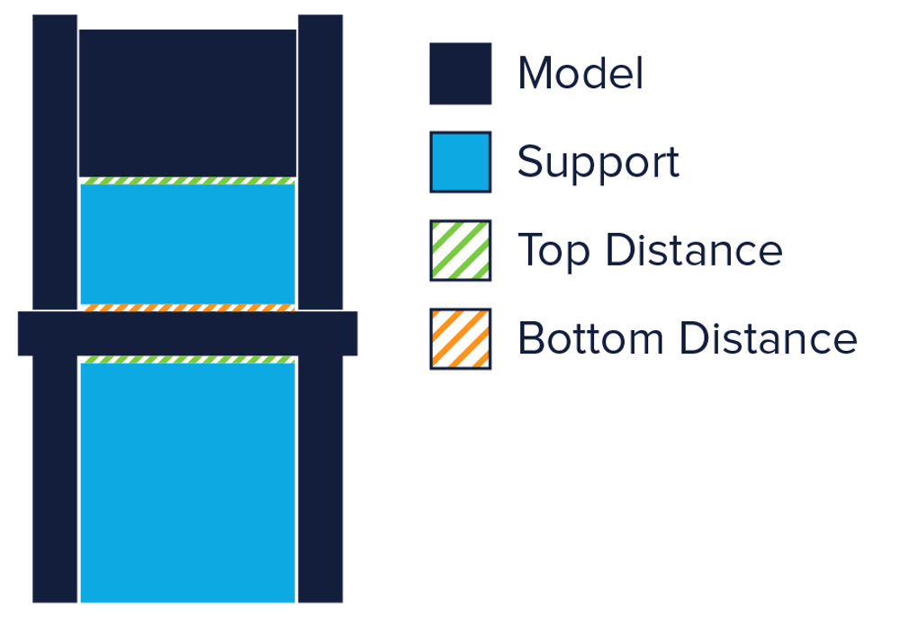
After reading this, especially this image and the verbiage about Support Z Distance, I think it’s clear that there are no pre-defined points of contact–at lease in the case of Cura.
Of course, I already removed the support and laid it on its side for the photo. The distance between the inside surfaces of the vertical rods on the sides is 35 mm.
The horizontal bar of the model is supposed to be 2.5 mm thick, but in the middle of the span it measures a bit more than 3 mm thick. You can kind of see it in the photo I think. That’s because the support was 0.5 mm away and so the filament sagged until the support stopped it from falling any farther.
Not pictured is another print where I used the default value of 0.16 mm for Support Z Distance, and the horizontal bar measures only slightly more than 2.6 mm thick on that print.
I didn’t try narrower distances for that test print, but that’s exactly what I had to do for Yoda’s eyes in my Baby Yoda print I posted. I kept having problems with the eyes breaking from from the supports and ruining the print. I finally succeeded by setting Support Z Distance to 0.05, but the print was much more fused to the supports. I had to use a hot knife to get the supports off.
By the way, after reading that All3DP link I posted above, I think my problem with printing the eyes was due to the way I was angling it on the build plate and it was actually the Support X&Y Distance that was causing me trouble.
I guess the better the printer is dialed in for overhangs, the better it prints supports, as the first layer on top of support is basically a giant overhang.
So a very effective part cooling is a must, so the filament strain cannot fuse with the layer above or below, when printed in the air.
@mochalatte Try Tree Supports for those eyes. Alternatively, try the Custom Supports plugin which lets the user define where to place supports (it is a bit kludgy). The alpha build of Prusa Slicer lets the user “paint” on custom supports (very nice! That along with its enhanced ironing feature might make me switch). S3D has good support features but it has been a long time since it was updated and the latest Prusa alpha build surpasses it (from what I’ve read).
Last night I got a surprisingly emphatic answer to my question about whether the model always touches supports. I turned on supports for the T Rex jaw print just in case since the overhang angles were more than 80 deg for the print:
By the way, this print also verified role of Support X/Y Distance and the Priority setting. The spacing in my print was much more than the 0.16 mm setting and that is because the I used the default settings of Support X/Y Distance = 0.8 mm and the X/Y distance overrides Z for priority.
Obviously, the one on the left shows some support points backlit & the right hand pic is direct sunlight. Ignore where the micro points are detached. I squeezed a little too hard when picking up the model. Is this what you’re getting @mochalatte? I noticed in the backlit photo that there are no micro support points in the vertical gap. 'Course, why would there be?


