I don’t really understand that alternate method; at least not yet. However, one thing I noted in repeating the procedure a few times is how tricky the procedure can be. There are quite a few steps, and they have to be executed pretty much perfectly. I can do them from memory right now, but I wouldn’t want to try to repeat them after having not done them for a couple of months.
With that test shape I outlined earlier, I’ve been playing with filleting. It seems that, when possible, it’s most advantageous to fillet sketches rather than paddings. 2 questions: [LIST=1]
Yes, it is the best way. Current FreeCAD has some issues with consistency, when earlier sketches get edited. E.g. when you take the first sketch and add a simple hole, it is possible that your model falls appart because of this issue (known as topology naming). The problem is that creating a circle in the first sketch will create new faces and new edges and cause FreeCAD to reassign previous set references on faces and edges wrongly. This is where fillets and chamfer fail first and tend to hop to a wrong edge, where they cannot work and the whole model stops being rendered properly. Same goes for sketches on faces of the model and external geometry.
This is the main reason I usually avoid external geometry as well as sketches on faces and thats the main reason I usually use datum planes as I can bind several sketches onto the same datum plane and if the datum plane goes haywire for some reason, I just need to reposition those and everything else falls back in place correctly. With a proper name of the datum plane it is easy to find the original position in case it fell appart.
But even with datum planes I tend to model around the origin, placing my DPs using known offsets like BaseSketch.constrain.FrameWidth/2 to get on the right side of a model.
This issue got a little better with recent FreeCAD releases, but it is far from being fixed. In fact this is the only issue that holds FreeCAD back right now. You can edit a model parametric right now using references mentioned above and it will work, but only until you edit something upstream of your build path. Then it silently fails.
There is actually an example in FreeCAD I use to check if the issue is still there. If you are on the start page of FreeCAD there are your latest projects and some examples. Load the PartDesignExample file. It looks like a key shaped castle wall. Now open the first pad named “pad” ![]() and enter the sketch within. You see a rectangle with an arc. Now make a small circle onto the radius of the arcs center. This should make a hole bottom to top in the “castles tower” and nothing else. If you close the model you will notice that the model looks different as the rectangular pocket moved from the top to the bottom of the model, due to the topology naming issue. The additional hole created a new face and the pocket got shifted to some random other face, which is on the floor of the model.
and enter the sketch within. You see a rectangle with an arc. Now make a small circle onto the radius of the arcs center. This should make a hole bottom to top in the “castles tower” and nothing else. If you close the model you will notice that the model looks different as the rectangular pocket moved from the top to the bottom of the model, due to the topology naming issue. The additional hole created a new face and the pocket got shifted to some random other face, which is on the floor of the model.
And now 2) ![]() Sketch filets are just normal segments of a circle. The tool just inserts them for you and sets a tangential constrain. Just click on the circular segment and define a radius. Done.
Sketch filets are just normal segments of a circle. The tool just inserts them for you and sets a tangential constrain. Just click on the circular segment and define a radius. Done.
Here is the other way to create the frame without a datum plane, but with two pads:
https://www.geit.de/tmp/FrameExample2.FCStd
I watched this video: [U]Fusion360 to FreeCAD - Introduction - YouTube. It helps F360 users adapt to FCAD. At one point he points out that 1 of the things being looked at for the next version of FCAD is support for multiple objects in 1 body. He also showed how it’s possible to do joins and cuts by creating bodies, selecting them together, then using the join and cut tools. That is way more like F360.
I never used Fusion360 in my life! ![]() The only other CAD software I “launched” was Blender on MorphOS, just to see if it works.
The only other CAD software I “launched” was Blender on MorphOS, just to see if it works. ![]()
Soooooo, just now I decided to revisit the headrest purse/bag hanger, but this time using F360. I’ve avoided doing that up until now because I was determined to do it in FCAD.
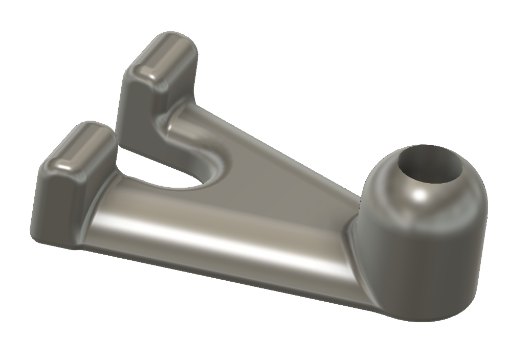
Wow, what a difference! True, I do not have much experience with FCAD, but I don’t have that much more with F360. Creating the hook in F360 was 100 times easier than in FCAD. It took me less than 10 minutes, and it was done using a single sketch. And, it also incorporates the “finger hole” I talked about earlier. Plus, it incorporates all the fillets I wanted, and they were absurdly easy to do.
Image captured from F360: [ATTACH=JSON]{“data-align”:“none”,“data-size”:“custom”,“height”:“233”,“width”:“345”,“data-attachmentid”:4408}[/ATTACH]
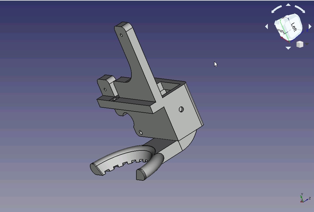
Image captured from FCAD after importing a STEP file exported from F360: [ATTACH=JSON]{“data-align”:“none”,“data-size”:“medium”,“data-attachmentid”:4409}[/ATTACH]
This experience makes it a lot harder to move away from F360. It also points out how FCAD needs a tremendous amount of development before it can compete with F360. Based on what I just did, and with the caveat that the list is not complete or even exhaustive, I take away these things that FCAD needs to incorporate or improve:
- when drawing a closed shape such as a rectangle or circle, adding dimensions should be part of the actual drawing process itself, not a separate function that has to be done later;
- the interior of all closed shapes should automatically become selectable faces;
- sketches must be able to have multiple closed shapes and not require the creation of separate bodies;
- closed shapes on a sketch need to be able to be extruded to different heights;
- filleting needs to be seriously improved.

In some points you are right, in others not. Like the one I picked. That is not the way it is intended to work.
What you do is checking how the windows desktop works and then blaming MacOS to do it differently.
This is a very nice channel, where more or less all CAD tools are shown.
https://www.youtube.com/channel/UC-C…NwC-3RBKUoAOQQ
I was amazed when I saw him model an WW Airplane or a Car in a few minutes using FreeCAD.
When it comes to testing builds, Fusion360 already fails as the simulation stuff is lacking in the free version. The videos in that channel show extensively what is possible in all CAD applications and he constantly compares the current workflow with the one used in other CAD tools.
The point is that you are used to Fusion and when I would swap to Fusion I would have difficulties to adapt my workflow, too.
On top of all that, keep in mind that FreeCAD is not developed by a company with hundreds of developers working 8 hours a day on the applications. FreeCAD gets developed by three hobbyists in their spare time plus a couple of people helping out and adding more workbenches to the mix.
Actually, I’m not picking on F360 or FCAD; they are just the current examples. When I say FCAD needs to be able to have multiple objects on 1 sketch, what I really mean is that any good CAD package should have this ability. The same applies to all the other points I made. It was just that I zoomed in on these ones because I noted how the 2 CAD programs are different.
I’m really not comparing apples (hehe) and oranges. I honestly don’t care whether FCAD is designed to work with multiple objects on 1 sketch. My point is that it is the way it should work. That, of course, is just my opinion, but there it is. Oh, and my understanding is the next version will allow multiple objects per sketch. Whether it will allow different padding heights, I don’t know.
I’m really not used to F360. I only have a few hours more experience with it over what I have with FCAD. It was very hard to get even a bit of a feel for F360, but FCAD has been much harder.
Sorry, but I don’t make allowances because FCAD is developed by 3 hobbyists. However it’s developed, the bottom line is my experience using it. I’m looking at the whole CAD thing from an agnostic point of view: which one is better to use, regardless of cost or how it’s developed. No, I would not pay $300+ per year to licence F360, but I would pay $50, which is what I do for my Untangle UTM. I do admire & applaud the FCAD developers for their efforts. It is a wonderful thing they’re doing, but their product is not where I believe it should be. I give them kudos, but I won’t make allowances. I don’t believe the idea of Open Source is to create sub-standard products. In the projects I worked on, my standard was to be state-of-the-art, not so-so-OK.
Thank you for the link. I will definitely look at it.
@Geit, I just wanted to update on the Joko Engineeringhelp videos. There is no doubt the guy is a maestro, with both FCAD and Solidworks. I doubt I could ever achieve anything close to his level of skill & expertise. I did note that he pointed out how FCAD is weaker than Solidworks when it comes to filleting. So, for the purse hanger, I guess F360 was my best option. That said, I’m not giving up on FCAD, at least not without giving it a good deal more effort.
I’m going to watch more of Joko’s videos to see what I can learn. I’m particularly interested in how he uses the XY, XZ, YZ, and Datum planes to orient different sketches in a project. I’m pretty sure I’ve been over-complicating my FCAD bodies with sketches.
Again, thanks for pointing me to his videos.
Yeah, at first I used references to faces, which - as I mentioned above - cause trouble and had a very bad time. Then I used DatumPlanes as work around, but they became very handy.
I now use them all the time, even sometimes when modeling on a standard plane to give it a name. Linking multiple sketches to a side of a model is just saving so much time on the long end.
Did this today:
[ATTACH=JSON]{“title”:“TronXYFanMount.jpg”,“width”:“320”,“height”:“216”,“data-align”:“none”,“data-attachmentid”:4420}[/ATTACH]
It is a two part fan shroud for the default TronXY X5, which is just blowing sideways onto the hotend, which currently needs kapton tape to be insulated from the air stream. This should be far better, cool both sides of the model and not the heater block.
Neat idea, and another demonstration of how you can make FCAD do what you want, if you know how.
After watching a few of the Joko Engineering videos on YT, I’m starting to think I might understand why they say that not allowing more than 1 solid per body is a deliberate design objective. I think it stems from the developers being primarily CNC oriented. IOW, they come from the perspective that you take a single body and cut things away until you have want you want.
To test this hypothesis, I once again created the top cap for a lithophane stand-up lamp I’m working on (I found a lamp close to what I’m looking for, but it tapers as it goes up, which I think will make the backlight uneven).
When trying to make this cap using additive techniques, I ended up with a bunch of bodies, because, I kept getting “too many solids” errors. And, the filleting was problematic, to say the least.
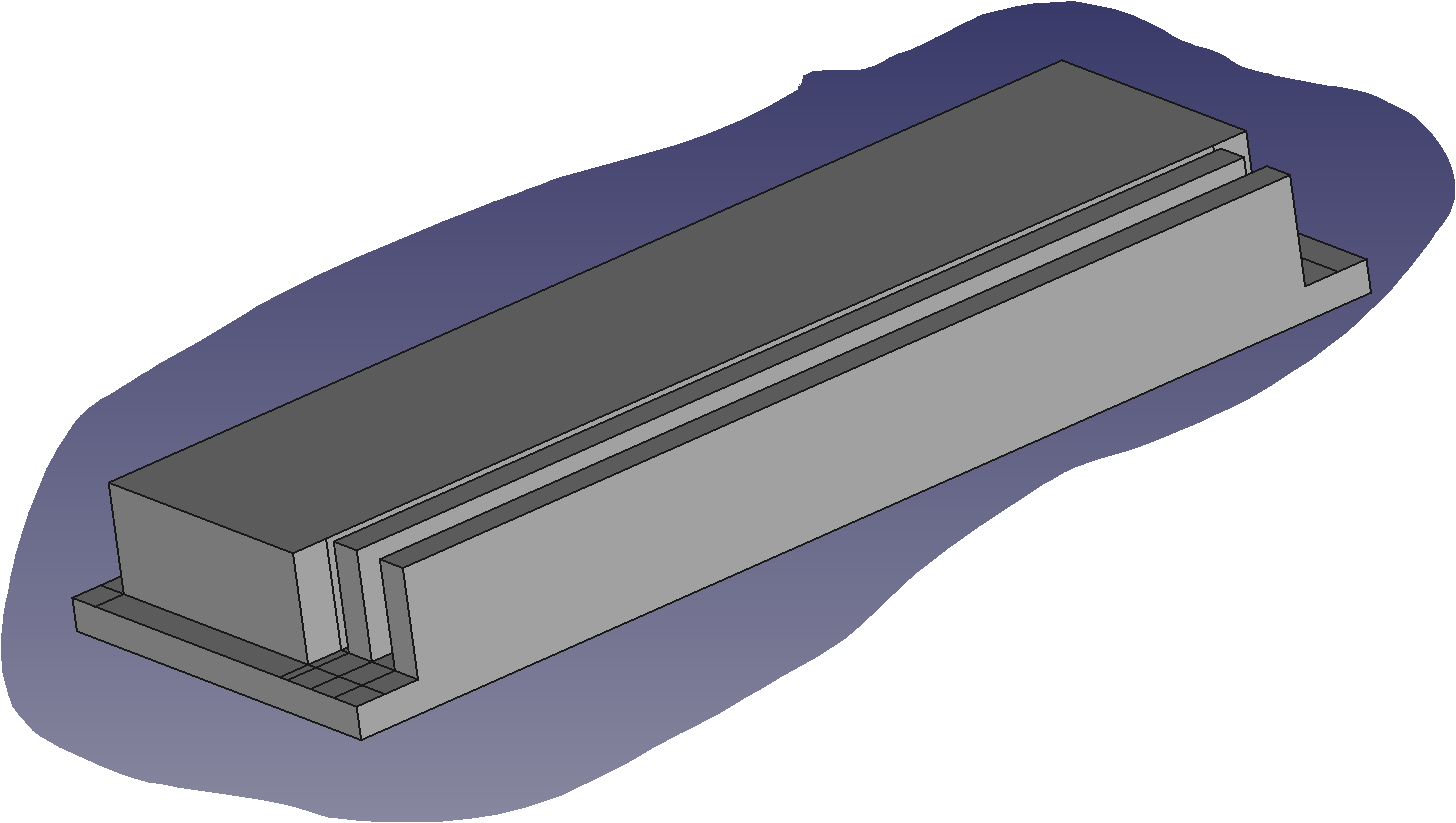
However, it seems you can have as many cutouts in a body as you like. I created a rectangle on a sketch where the X & Y measurements were the maximum needed. Then I padded the rectangle to the maximum Z measurement. I ended up with a block 107mm x 37mm x 13mm. Then I started creating sketches on various faces of the block and using the Cutout tool to shave off parts of the block. There was no requirement to create a 2nd, 3rd, or more bodies in order get the desired result.
Here are some screen captures of the process I used:
[ATTACH=JSON]{“data-align”:“none”,“data-size”:“medium”,“data-attachmentid”:4449}[/ATTACH] [ATTACH=JSON]{“data-align”:“none”,“data-size”:“medium”,“data-attachmentid”:4451}[/ATTACH] [ATTACH=JSON]{“data-align”:“none”,“data-size”:“medium”,“data-attachmentid”:4450}[/ATTACH] [ATTACH=JSON]{“data-align”:“none”,“data-size”:“medium”,“data-attachmentid”:4452}[/ATTACH]
Does anyone else think this looks an awful lot like what would happen on a CNC Milling machine?
And, finally:
[ATTACH=JSON]{“data-align”:“none”,“data-size”:“medium”,“data-attachmentid”:4448}[/ATTACH] Yep, it took quite a few steps, but it actually worked pretty well, and the fillets worked without issue.


What is it supposed to look like when it’s done? Where does the light source go?
What you see is only the top cap. It’s the smallest part of the lamp, which is why I worked on it first.
Here’s a very rough sketch of the idea. It’s not finalized by any means.
[ATTACH=JSON]{“data-align”:“none”,“data-size”:“medium”,“data-attachmentid”:4456}[/ATTACH]

OK I see. Looks interesting.
The plan is to put about 3 short strips of 5volt white LEDs onto the back wall behind the litho. I want to shape the interior of the base section so a female USB connector can be mounted inside, along with a rotary control to manage brightness. Plug a USB cord into the socket and it lights up. The only accessories needed would be a USB cable and USB wall adapter. I might put 4 small rubber feet on the bottom.
Any plans to put a rechargeable battery inside so that it couls walk around?
I thought about it, but ultimately decided “no”. I didn’t feel the advantages were worth the time & effort required.
I can understand that. It seems to add a lot of complication.
Although it might get used for other purposes, my main reason for designing this lamp is to give it to a neighbor who lost a son in a car accident. I have photo of his son at around 5 years old that I plan to use for the litho. If he likes it and wants, I might also print another litho of his son when he’s older.